
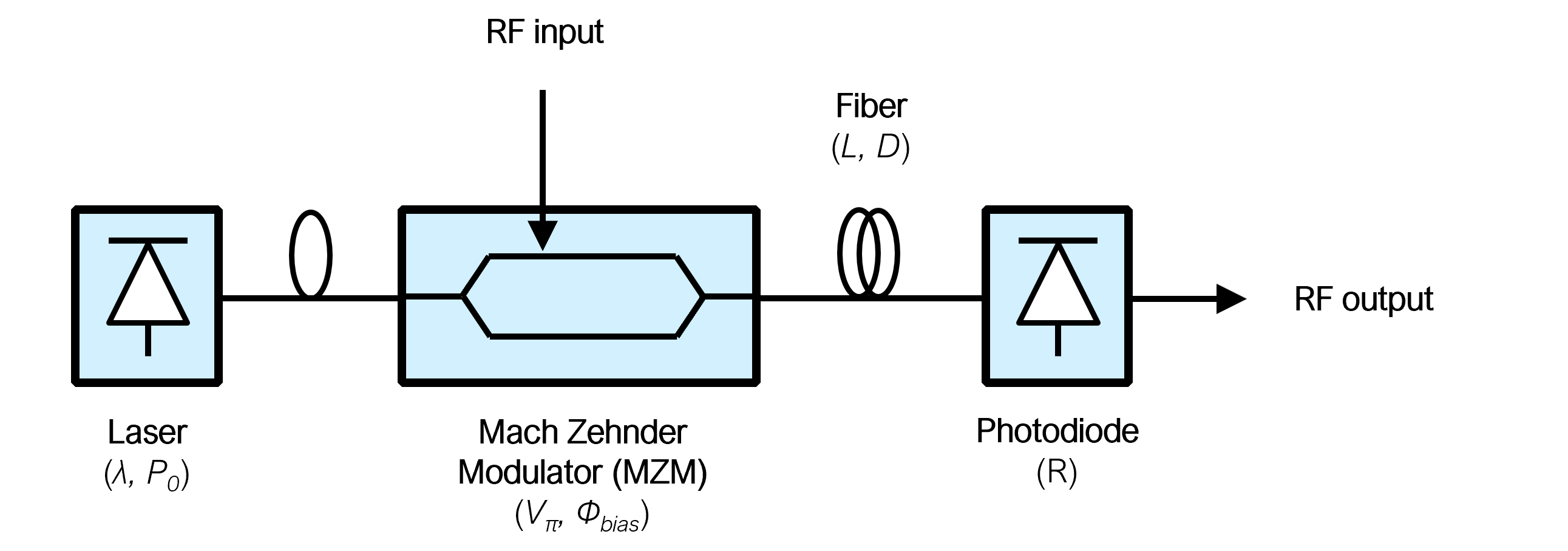
Radio-over-fiber (RoF) link model aims to represent an external modulation analog optical link, with radiofrequency input and output ports.
The working principle of these devices is the modulation of the RF input over an optical carrier (generated by a light source - typically a laser), by means of an electro-optic modulator (EOM). Once in optical domain, the signal can travel an optimal fiber of certain features and finally converted back to RF domain by means of a photodetector [1].
The obvious advantage of such a device is the radio signal transmission with (almost) distance-independent losses, as optical fibers feature losses as low as 0.02 dB / km. Nevertheless, many other applications are found by exploiting devices nonlinearities, such as mixing links [2] (wideband downconversion/upconversion).
This particular model assumes a Mach-Zehnder Modulator (MZM) is used. Extensive amounts of documentation are available to be read, as these EOM devices are very-well known, are widely commercially available and have been thoughfully studied and used in several applications.
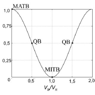
The model allows to choose the biasing point of the Mach-Zehnder Modulator (MZM), defined in degrees following:
The selection of such biasing point allows to simulate RoF analog links in the different well-known operation points of the MZM transfer function, and in any intermediate:
The following analytical expressions for gain, noise and non-linearity are used, which can be derived from bibliography [1].
For the gain, calculation is based on the RMS photocurrent of the fundamental electrical frequency:
Where P0 is the laser source power in W; Lmzm are the insertion losses of the MZM in linear units; Lfiber are the fiber losses in linear units; R is the responsivity of the photodiode in A / W; ERmzm is the extinction ratio of the MZM in linear units.
Note that in the previous expression, P0 is divided by a factor of 2 (-3 dB) given that the maximum fundamental transmission is happenning at QB point, with 3 dB optical power suppression. For the case of QB:
Considering that ERmzm contribution can be neglected for the QB case.
From such photocurrent, the analog link gain for the fundamental electrical frequency can be seen as:
From where it can be extracted the following rules for gain scaling, confirming the experimental observations of such kind of analog links:
HD(f) is the frequency response due to periodic carrier suppression happening in optical fiber due to chromatic dispersion [3-4].
Where L is the fiber length in km; D is the fiber optic linear dispersion in ps / (nm * km); λ is the laser center wavelength in nm; c0 is the lightspeed in the fiber medium in km/ps.
Hrolloff(f) is a N-th order pole lowpass frequency response, which is already explained in the Cable model documentation.
Optical power in the photodiode and mean (DC) photocurrent are the main drivers for relative-intensity noise (RIN) and shot noise powers. They can be calculated as:
Where all involved variables have been already commented. Then, noise power can be calculated as:
Where k is the Boltzmann constant; T is the temperature in Kelvin; q is the elementary charge in Coulombs; RIN is the laser Relative-Intensity Noise in dBc/Hz. One can see that noise power dependency on DC photocurrent (and, thus, on photodiode optical power) is different for each noise contributor, namely:
Out of noise contributions, noise figure of the analog link can be modeled as [1]:
Where g(f,φmzm) is the already analyzed analog link gain.
Input P1dB and IP3 in an analog link for the maximum linearity point (QB) are determined by the MZM transfer function, and can be calculated as follows:
Corresponding output P1dB and IP3 can be calculated just by applying the analog gain.
For the case of second-order intermodulation intercept point OIP2, it is modeled by calculating first HD2 gain in terms of φmzm, similarly as done above for the fundamental frequency but using the opposite trigonometrical relation:
Finally, HD2 respect to fundamental carrier, and then OIP2 and IIP2, can be calculated just as:
The model includes the following properties:
| Property | Description | Units* |
|---|---|---|
| L | Fiber length | m |
| D | Fiber optic linear dispersion | ps / (nm * km) |
| alpha | Fiber optic carrier attenuation | dB / km |
| carrier_lambda | Laser source center wavelength | nm |
| P0 | Optical power of the laser source | dBm |
| RIN | Relative intensity noise of the laser source | dBc / Hz |
| R | Photodiode responsivity. | A / W |
| MZM_Vpi | Vπ of external modulator. | V |
| MZM_IL | Insertion loss of external modulator. | dB |
| MZM_ER | Extinction ratio of external modulator. | dB |
| MZM_theta | Phase of external modulator bias (0 for MATB, 90 for QB, 180 for MITB). | deg |
| f_cutoff | Cutoff frequency | GHz |
| cutoff_order | Order of the cutoff pole | - |
*Units note: Please mind that units in block properties are selected for the best user convenience, and they might not match the units in the above model formulas. All the needed conversions are done as needed.
The RoF link model provides detailed information of intra-block working conditions for the given property values, including photodiode power, DC current and noise power (thermal, shot and RIN).

The following parametric sweeps show the model behavior as the different properties are changed:
Parametric sweep over L (1,000 to 10,000 meters) - Dispersion free
Very little gain difference over length, as expected (using typical single-mode fiber loss of α = 0.02 dB/km). Less than 0.5 dB difference between 1 and 10 km fiber length, which is consistent with 9 km loss (0.18 dB optically, then twice -0.36 dB- after photodetection).

Parametric sweep over L (1,000 to 10,000 meters) - Dispersion 17 ps / (nm * km)
When including non-zero dispersion (like standard single-mode fiber), periodic carrier suppression effects can be observed which depend on frequency and fiber length.

Parametric sweep over P0 (8 to 22 dBm) As expected from bibliography, radio link gain depends cuadratically on laser power (2 dB gain per dB of optical power), due to the cuadratic nature of photodetection.

Noise figure decreases with optical power, although not linearly (less than 1 dB per dB), as RIN noise starts to dominate towards higher optical powers.

OIP3 follows the same trend as gain, as IIP3 remains constant over optical power (dominated by Mach-Zehnder modulator transfer function).

Parametric sweep over MZM_theta (0 to 360 deg)
Radio gain shows a periodic behavior with MZM_theta, where the maximum gain is achieved in 90 and 270 deg (QB, as expected from MZM biasing concept explained above), whereas suppression occur in integer multiples of 180 deg (MITB, MATB).

Noise figure is minimized near MITB (180 deg), as photodiode optical power is also minimized and so does the relative-intensity noise (RIN) and shot noise contributions.
When exactly at MATB and MITB, the sharp drop of the gain contributes also to degrade noise figure significantly. In the intermediate area, noise grows together with optical-power-related noise contributions.

OIP2 is maximized in QB (90, 270 deg) and minimized in MITB, MATB (multiples of 180 deg). Consequently, second-order intermodulation products are suppressed in QB and maximized in MITB, MATB.
Note that, while gain evolves smoothly around QB, OIP2 evolution around QB is very sharp. Therefore, one can see the importance of a very precise biasing-tracking for external modulation links to ensure second-order products are minimized, specially for multi-octave operation where HD2 and IM2 limit the dynamic range.
Note also that applications exploiting second-order intermodulation (like photonic up/downconverters) would then choose to work in some point close to MITB (low-bias), which maximized second-order intermodulation while keeping noise figure as low as possible, and still reasonable gain. Gain losses due to the use of low-bias points (near MITB) might be recovered by using higher optical powers.

[1] Cox, Charles H., "Analog Optical Links: Theory and Practice". Cambridge University Press 2004.
[2] Gopalakrishnan, Ganesh K. et al., "Microwave-Optical Mixing in LiNbO3 Modulators". IEEE TRANSACTIONS ON MICROWAVE THEORY AND TECHNIQUES, VOL 41, NO 12, DECEMBER 1993
[3] Meslener, George J., "Chromatic Dispersion Induced Distortion of Modulated Monochromatic Light Employing Direct Detection". IEEE JOURNAL OF QUANTUM ELECTRONICS, VOL. QE-20, NO. 10, OCTOBER 1984
[4] Sharma, Vishal et al., "Challenges to radio over fiber (RoF) technology and its mitigation schemes – A review". Optik Volume 123, Issue 4, February 2012, Pages 338-342
[5] Yao, Steve et al., "Influence of an Externally Modulated Photonic Link on a Microwave Communications System". Telecommunications and Data Acquisition Progress Report, TDA PR 42-117, January-March 1994, pp. 16-28
[6] C.H. Cox; G.E. Betts; L.M. Johnson, "An analytic and experimental comparison of direct and external modulation in analog fiber-optic links". IEEE Transactions on Microwave Theory and Techniques (Volume: 38, Issue: 5, May 1990)