
Microstrip line model aims to represent propagation over a microstrip transmission line with a given geometry.
The core of this model is the scikit-rf library MLine class which is based on qucs project sources [2].
The used quasi-static characteristic impedance and effective permittivity model is from Hammerstad & Jensen [3]. The frequency dispersion of impedance and effective permittivity model is from Kirschning and Jansen [4].
Based on this model, Radio System Toolbox includes also an standalone calculator application to find the optimal width of a microstrip line for a given characteristic impedance (Z0) based in the substrate geometry. It also calculates the effective permitivity εr eff, group delay and losses per unit of length.
The calculator can also determine the characteristic impedance of a microstrip line, for a given strip width.
The model includes the following properties:
| Property | Description | Units* |
|---|---|---|
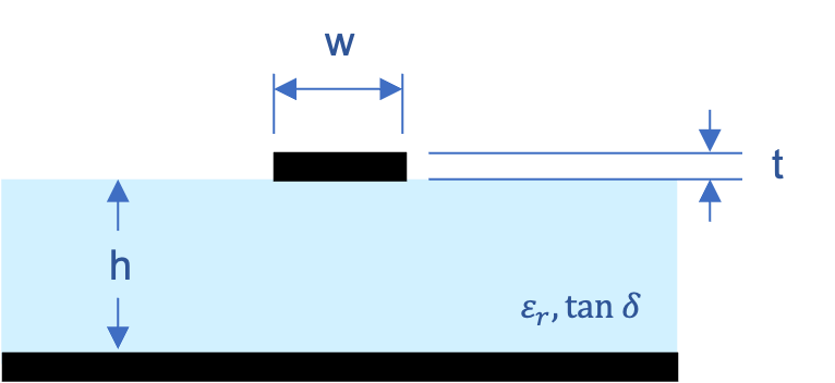
| L | Trace length | mm |
| W | Line width | mm |
| h | Substrate height | mm |
| T | Line thickness | mm |
| Substrate | Substrate id from Radio System Toolbox substrate library | - |
| E_r | Relative dielectric constant. It will be ignored is Substrate is defined. | - |
| tand | Dielectric loss tangent. It will be ignored is Substrate is defined. | - |
| rho | Conductor resistivity | Ohm / m |
| rough | Conductor roughness | m (RMW) |
*Units note: Please mind that units in block properties are selected for the best user convenience, and they might not match the units in the above model formulas. All the needed conversions are done as needed.
The following parametric sweeps show the model behavior as the different properties are changed:
Parametric sweep over W (0.2 to 1.0 meters)
It can be observed that minimum ripple in gain can be achieved for W = 0.4 mm or W = 0.5 mm (which are the closest to the optimal, 0.418 mm).

Parametric sweep over tand (0.0001 to 0.05 GHz)

Parametric sweep over L (20 to 40 mm)
Ripple resonance period reduced with transmission line length, as expected.

Radio System Toolbox offers tools to calculate the optimal line width to achieve a target characteristic impedance (Z0) based in the substrate geometry. You can either:
For a given microstrip line block added to your project, with some badly chosen "W" value (1.2 mm in this example, for a E_r = 9.6 and h = 0.508 mm among others), your S-parameters would look like the following picture, with significant ripple and return loss:

In fact, we can use our standalone Microstrip Calculator to check the expected characteristic impedance of this line. It is not a surprise that it shows such a bad behavior, as it is Z0 = 30.49 Ω.

By clicking shortcut button "Match 50 Ω width", the optimal line width "W" will be calculated (in this case, it is found to be 0.41816 mm). S-parameters look much better matched, with very reduced ripple in S21 and very reduced return loss.
